CCNA Key Notes


Protocols
Host Communications Terminology
PDUs: Protocol Data Units
When 2 hosts communicate with each other, they exchange the PDUs.
PDU is the entire communication all the way from Layer 7 to Layer 1 of OSI stack.
This further can be divided into different terms: Data (TC/IP > Application Layer); Segment (TCP/IP > Transport Layer); Packet (TCP/IP > Internet Layer); Frame (TCP/IP > Network Access Layer).
OSI Model
Application Layer (7)
Provides network services to the applications of the user.
Differs from other OSI layers; doesn't provides services to any other OSI layer.
Establishes availability of intended communication partners.
Then synchronizes & establishes agreements on procedures for error recovery & Data Integrity (Data Integrity means: checking the data has not been altered or corrupted in transit).
Presentation Layer (6)
Ensures that the info sent by the application layer is readable by the application layer of the other system.
Can translate among multiple data formats using a common format (e.g. Computers with diff encoding scheme).
Session Layer (5)
Establishes, Manages & Terminates sessions between two communicating hosts.
Also, syncs the dialog between presentation layer of the two hosts & manages their data exchange.
Example: Web servers have many users, so there are many communication processes open, at any given time to track.
Transport Layer (4)
Note: TCP -> for more reliability between 2 hosts || UPD -> for more speed (eg: Voice/Video).
Main characteristics of L4 is whether TCP / UDP transport is used & the port number.
Definition
The transport layer defines services to segment, transfer and reassemble the data for individual communications between the end devices.
It breaks down large files into smaller segments that are less likely to incur transmission problems.Extras:
- Flow control is the process of adjusting the flow of data from the sender to ensure the receiving host can handle it.
- Session Multiplexing: Host is able to support multiple sessions simultaneously & manage individual traffic streams over single link.
- Stateful Firewalls: If traffic was initiated by the Sender (left) -> to -> Receiver (right), then it would allow to get back <- from right to left, if it was initiated by the sender. Or else, it will deny if initiated from right to left.TCP
Transport Control Protocol > Connection oriented: Once connection is Established, data is sent bidirectional.
Carries out sequencing to ensure segments processed in correct order.
Reliable: receiving host send ack to sender. Lost segments are reset.
Performs Flow Control.
Three-way handshake: Syn (->) >>> Syn-Ack (<-) >>>> Ack (->).
TCP Header: Source Port (16); Destination Port (16); Sequence number (32); Acknowledgement number (32); Header Length (4); Reserved (6); Code Bits (6); Window (16); Checksum (16); Urgent (16); Options (0 or 32 if any); Data (Varies).
UDP
User datagram Protocol: Not connection oriented; No Handshake connection; Doesn't carry sequencing; Not reliable; No Flow Control.
UDP Header: Source port; Destination Port; Length; UDP Checksum; Data.
Applications & Destination Ports:
TCP: FTP (21); SSH(22); Telnet(23); HTTP(80); HTTPS(443).
UDP: TFTP(69); SNMP(161).
TCP & UDP: DNS(53).
Network Layer (3)
Most info at L3 is source & destination IP address.
Routers operate at L3.
Definition:
Provides connectivity & path selection between two host systems that may be located on geographically separated networks.
This layer manages the connectivity of hosts & provides logical addressing.
Extras
TCP/UDP at L4 || IP Addresses at L3 || MAC Address at L2 ||
L3 separates the overall network into small "Subnets".
IP Header (32 bits) at L3
First Row:
- 4-bit version > IPv4 / IPv6
- 4-bit Header length > Can be different length because it varies.
- Type of Service > example VOIP traffic, so this can help to provide the quality of service accordingly.
- 16-bit total length (in bytes)Second Row:
- 13-bit fragment offset > Example: Ethernet max transmission unit size, max size by packet. Max size by default in eth is 1500 byte MTU. So, if it's more than that then it will split in parts called Fragments. IP header 2nd row is used to track Fragments.Third Row:
- 8-bit time to live (TTL) > Every time a packet goes through a router the router will decrement the TTL field by one. If it gets down to Zero, then that router will drop the packet. Used to prevent Routing loops.
- 8-bit protocol > Specifies L4 -- TCP / UDP.
- 16-bit header Checksum > checks the packet has not been corrupted in transit.Fourth Row:
- 32-bit Source IP address.Fifth Row:
- 32-bit Destination IP address.Sixth Row:
- Header Options, if any (0-40 bytes) > Can put additional information, not usually used.Seventh Row:
- Data (Variable length) > the rest of the packet.
Unicast, Broadcast & Multicast Traffic
Unicast: One sender sends one separate copy to different hosts. suppose it is a video of 1MB then, it will send 3 different video copies to 3 different hosts. Total of 3MB worth of bandwidth.
Broadcast: One sender can send to multiple hosts via switch. Forwards everywhere.
Note: Routers do not forward broadcast traffic on. They drop the packets received from Switch.
Multicast: Same as Broadcast traffic but, in Broadcast, it forwards everywhere. Whereas, in Multicast, it forwards to only those who have requested/targeted. Example - Radio voice: it forwards to only those who are on that particular radio station.
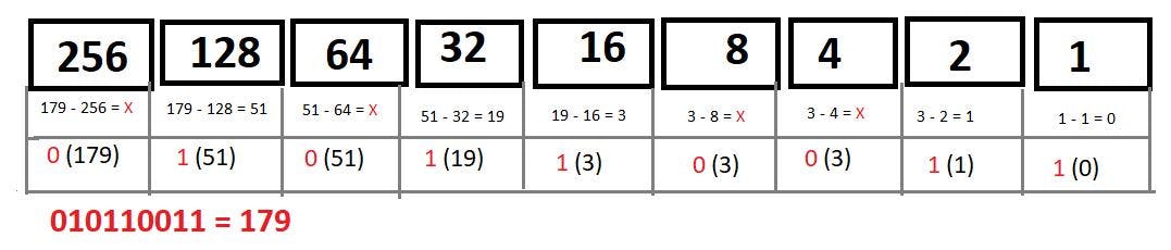
Decimal to Binary Conversion
Converting 179 to Binary
Subnet Mask in Slash Notation
If the subnet mask is /255.255.255.0; who's decimal conversion is [11111111. 11111111. 11111111. 00000000] >> Here, there are 24-times 1's. So, it is /24.
If the subnet mask is /255.255.0.0; who's decimal conversion is [11111111. 11111111. 00000000. 00000000] >> Here, there are 16-times 1's. So, it is /16.
IP Address Classes
Class A IP addresses
- First octet ranges between 1 to 126
- Default subnet mask (/8) 255.0.0.0
- Valid range between 1.0.0.0 to 126.0.0.0/8
- Can be assigned to Host.
Class B IP addresses
- First octet ranges between 128 to 191
- Default subnet mask (/16) 255.255.0.0
- Valid range between 128.0.0.0 to 191.255.0.0/16
- Can be assigned to Host.
**Class C IP addresses
**- First octet ranges between 192 to 223
- Default subnet mask (/24) 255.255.255.0
- Valid range between 192.0.0.0 to 223.255.255.0/24
- Can be assigned to Host.
Class D IP addresses
- First octet ranges between 224 to 239
- Has no default subnet mask.
- Valid range between 224.0.0.0 to 239.255.255.255
- Used in Multicast.
Class E IP addresses
- First octet ranges between 240 to 255
- Has no default subnet mask.
- Valid range between 240.0.0.0 to 255.255.255.255
- Used in Experiments.
- 255.255.255.255 is Broadcast network for "this network".

Data-Link Layer (2)
Source & Destination Layer 2 address is most important here.
Example: Source & Destination MAC address if Ethernet is the Layer 2 Technology.
Switches operate at Layer 2.
Definition:
It defines how data is formatted for transmission and how access to physical media is controlled.Includes error detection and correction to ensure a reliable delivery of the data.
Physical Layer (1)
Concerns physical components of the network, for example the cables being used.
Definition:
Physical link enables bit transmission between end devices.
Defines specification needed for activating, maintaining & de-activating the physical link between end devices.
Example: Voltage levels, physical data rates, maximum transmission distances, physical connectors etc.
Commands Shortcuts
hostname> User exec modehostname# Privileged Exec mode ('Enable')hostname(config)# Global Config mode ('Configuration Terminal')hostname(config-if)# Interface config mode ('interface x')Ctrl+A moves the cursor to the beginning of the line.Ctrl+U deletes the whole line.show running-config | exclude interface Will exclude interface worded lines.show running-config interface FE0/0 | section bgp Will show BGP configs of that int.hostname(config)# do show interfaces brief When in config mode, can use do show for interface info.
IOS Configuration Management
- To make config changes:
Router# conf t>Router(config)# hostname Router1& you'll getRouter1(config)#
Note: Commands entered, or config changed in running-config do not get saved automatically. You need to copy it to startup config. Startup config means, whenever the Router is started the next time or rebooted, the configuration remains same.
To save the configs to startup-config: Go to privileged exec
Router1#> run the commandcopy run startand then they will ask where we want to save ? can keep it default.To BACKUP the config:
copy run flash:my-confighere, flash:<give your file name>. Then destination, can keep it default. And it's backed up. Can verify it by runningshow flash& can see "my-config".To restore it back: You'll first have to erase the existing startup configs, to avoid merging of commands. Run
erase startORwr eraseand this will erase nvram files system.
Then runRouter# copy flash:my-config startand this will copy config to startup config. Need to reboot the router.
Note: Copying backup on same router on flash is bad practice, need to copy on tftp serverisntead.
To do so: Router# copy run tftp > enter tftp (Trivial File Transfer Protocol / port69) IP address > Enter file name. Then it will backup on that tftp server in text file.
Configuration Storage Locations:
IOS operating system image stored in Flash.
Startup Configuration in NVRAM.
Running Configuration in RAM. [Loaded in RAM from Startup Config when device reboots].
Interfaces and Cables
Ethernet standards (copper):
Speed > Common Name > IEEE Std > Informal Name > Max Length
- 10 Mbps > Ethernet > 802.3i > 10 Base-T > 100mtr
- 100 Mbps > Fast Eth > 802.3u > 100 Base-T > 100mtr
- 1 Gbps > Gigabit Eth > 802.3ab > 1000 Base-T > 100mtr
- 10 Gbps > 10 Gig Eth > 802.3an > 10GBase-T > 100mtr
- Copper cables used in Ethernet standards are UTP cables.
UTP stands for: Unshielded Twisted Pair > Have no metalic shield >Twisted Pair helps to protect against EMI (Electromagnetic Interference). > Has 8 pins > Pair of 2.
10 Base-T & 100 Baste-T uses 2 Pairs (4 wires)
1000 Base-T & 10GBase-T uses 4 Pairs (8 wires).
Copper UTP Cables
Note: Copper UTP wire can be used up to 100mtrs.
Full Duplex Transmission
Both devices can send & receive data at the same time with no problems like collisions will occur as, they use separate wires to transmit & receive data.
For example: PC -> SW
1st & 2nd Pin on PC will transmit data to SW at 1st & 2nd Pin (receives). And then 3rd & 6th Pin of SW will transmit data to PC at 3rd & 6th Pin of PC (receives), respectively.
Note: PC usually connects to a Switch; and a Switch usually connects to a Router.
How does Router's network interface work?
\> Same as PC's. A Routers' network interface's 1st & 2nd Pin is used to Transmit data and 3rd & 6th Pin is used to receive data from Switch. And the role of Switch is same as in previous case.
Straight-through Cable (10 & 100 Base-T)
Routers, Firewalls & PC transmits data on pins 1 & 2 AND receives data on pins 3 & 6.
Switches are opp., they receive data on Pins 1 & 2 AND transmits data on Pins 3 & 6.
Cross-over Cable (10 & 100 Base-T)
SW to SW connect: Pin 1 & 2 (Left/receive) will connect on Pin 3 & 6 (right/transmit). Pin 3 & 6 on Left (transmit) will connect on Pin 1 & 2 on right (receive). And same for PC to Router via Crossover Cable.
Network Interface Card
It is a hardware component present in our device. Used to connect different networking devices such as PCs, servers and share data over the connected network.
Also known as: Network Adapters, Physical Network Interface, LAN Adapter, Network Interface Controller.
There are 2 types of NICs:
- Wired NIC : connected using RJ45 cables.
- Wireless NIC: Example, Wi-Fi connection.
For 100 Base-T & 10GBase-T
Switches, PCs & Routers uses all 8 pins (4 Pairs). Each pair is Bidirectional, means > each pair isn't dedicated specifically to transmitting or receiving data.
Fiber Optic Cable
Uses separate cables instead of separate wires unlike UTP Cables. It has 4 parts:
- Fiberglass core: Light is transmitted from this to transmit data
- Cladding that reflects light
- Protective buffer: Protects fiberglass from breaking
- Outer jacket of the cable